SigFit’s active control simulation allows the user to predict the best corrected surface of an active optic. This capability is useful in design development of active optics.
The surface deformation predictions to be corrected may be specified by a finite element analysis or by test data. Predictions of the acuator influence functions are specified in a similar manner and may have actuator stroke limits associated with them.
Augment actuator cases, which are generated internal to SigFit, may also be specified. Augment actuator cases are commonly used to remove the best fit plane and/or power to simulate focus correction or the inability of a metrology test to see such deformations.
The predicted corrected surface may be fit with polynomials, sent to an optical analysis input file, interpolated to an array, and viewed graphically with nodal result files. The following table shows an example of the printed summary output for active control analysis. The table shows the disturbance to be corrected, the input surface minus its best-fit-plane motion, and the corrected surface expressed as RMS errors.
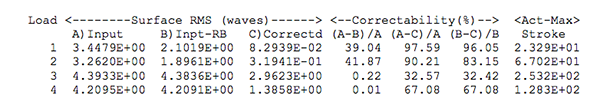
Additional printed output includes the predicted strokes of each actuator and the polynomial fit to the corrected surface. Other output forms such as array interpolation or optical analysis import files may be generated as well.
Example: Active Control Simulation of Thirty-Meter Telescope (TMT) Warping Harness Using SigFit
All material below is courtesy of TMT, Vincent M. Stephens, and Eric Williams. For more information on TMT please visit www.tmt.org.
TMT is a ground-based Ritchey-Chretien astronomical telescope scheduled for first science in 2022 on Mauna Kea in Hawaii. The design calls for a primary mirror thirty meters in diameter comprised of 492 actively controlled segments. Each primary mirror segment is supported by a set of three whiffletrees that include motorized warping harnesses with a total of 21 actuators. The Primary Segment Assembly, shown in Figure 1, is passively supported with warping harnesses providing a means for figure corrections to be performed about every two weeks. Out-of-plane rigid body control (piston/tip/tilt) is provided by means of the 3 position actuators and twelve edge sensors.
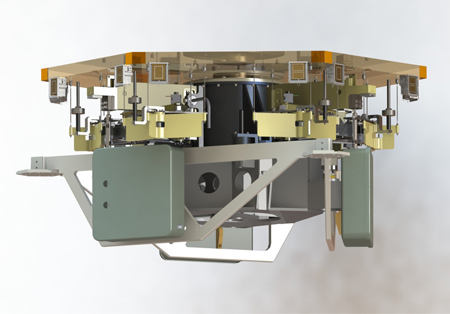
Figure 1: Illustration of warping harness and primary mirror segment for TMT.
The requirements for the active correctability of each segment are defined by correction factors for a set of prescribed deformations defined by Zernike polynomial terms. SigFit was used to predict the active control performance through the design development process. Results of the final design were shown to meet the correctability requirements as shown in Table 1.
Table 1: Correction Requirements for TMT Segments
|
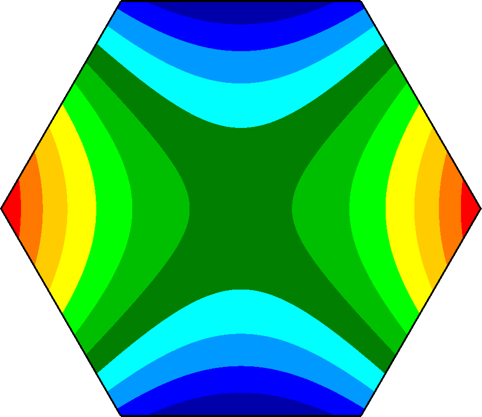
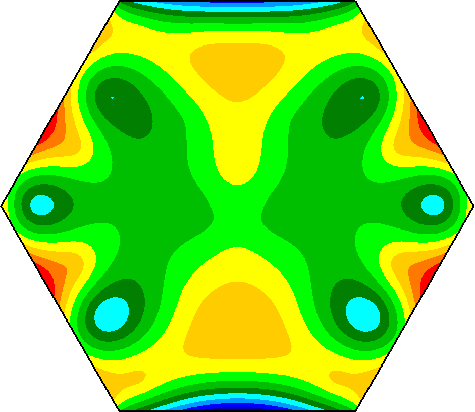
Figure 2: (a) Uncorrected 1200nm of astigmatism surface figure error and (b) corrected surface prediction.