SigFit supports design optimization in finite element analysis tools by writing files containing multipoint constraint equations and/or design response equations.
The content of these files allow optical performance metrics to be computed as design responses in design optimization analyses conducted in finite element analysis software. Responses for which equations may be generated are shown in the table below.
|
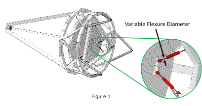
In this example the flexure mounts supporting the primary mirror of a telescope are being optimized. In the current design the jitter line-of-sight error is exceeding the requirement of 20 microns while the thermally induced deformation to the primary mirror is within the requirement of 0.01 surface RMS waves. The goal of the optimization is to minimize the line-of-sight error while keeping the surface RMS error within the specification.
An initial manual trade study considered the diameter of the primary mirror mount flexures as the only design variable, as shown in Figure 1.
The performance is constrained by the 0.015 waves surface RMS error requirement and yields a minimum line-of-sight error of 16.8 microns, well above the 10 micron requirement, as shown in Figure 2.
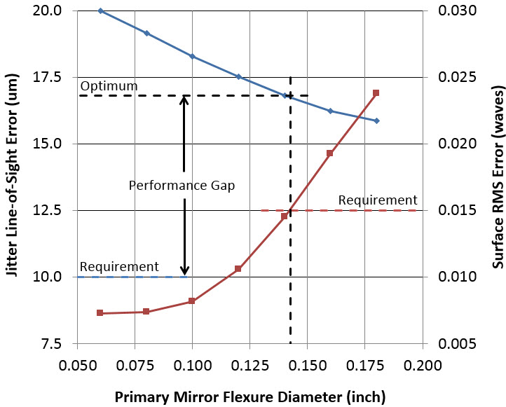
Figure 2 – Trade study plot showing optimum jitter line-of sight error constrained by surface RMS error for only one design variable.
In order to achieve the desired jitter line-of-sight error performance of 10 microns more design variables will need to be considered. Multiple design variables make manual trade studies difficult and incomplete, but the application of design optimization techniques is an effective way to obtain useful results. However, in order to employ design optimization the jitter line-of-sight error and surface RMS error must be computed as design responses in the form of equations within the finite element tool in which optimization is being performed.
SigFit is used to generate these equations in MSC Nastran format for design responses of the jitter line-of-sight error and the primary mirror surface RMS error. The jitter line-of-sight equation is used in a random response subcase of a design optimization analysis while the primray mirror surface RMS error equation is used in a thermoelastic static deformation subcase. When used with several design variables of the metering structure an optimum design is found that meets both optical requirements and has a minimum weight.