SigFit’s interface to SolidWorks Simulation makes it easy to access FEA results for optomechanical analysis. |
 |
With a few simple steps the SolidWorks Simulation model is prepared for interface with SigFit. Described below is the workflow to bring the results of mechanical simulations into SigFit.
Preparation of SolidWorks Model for SigFit Analysis
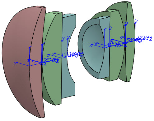
Creation of Vertex Coordinate Systems
Rectangular coordinate systems representing surface coordinate systems in the optical analysis model are created by the user within the SolidWorks model. The user is free to locate these coordinate systems anywhere within the SolidWorks model tree.
[margin20]
Definition of SigFit Analysis
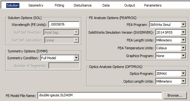
Point to Assembly or Part File
The user defines chooses SolidWorks Simulation and the version for the FEA software to which to interface. Units specifications for length, temperature, and stress are allowed depending on the analysis type and must be consistent with values of properties defined in SigFit. Either an assembly or part file may be referenced as the model file. SolidWorks Simulation must be running and active in order for SigFit to interface to the finite element model and results.
[margin20]
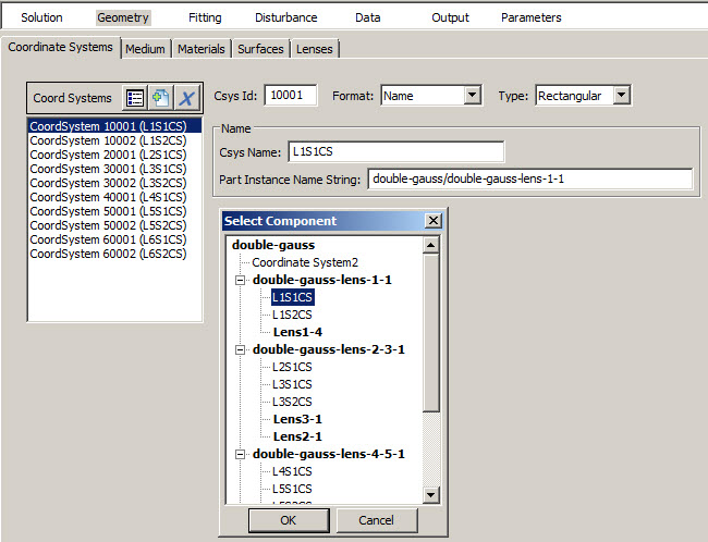
Reference Vertex Coordinate Systems
Rectangular coordinate systems representing surface coordinate systems in the optical analysis model are referenced and assigned an integer ID number for use in SigFit.
[margin20]
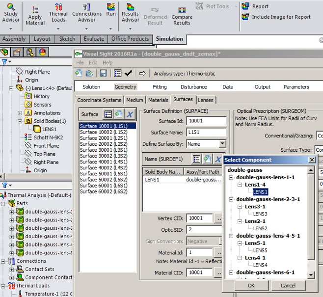
Define Surfaces and Link to SolidWorks Simulation Model
Surface entities are defined in a manner similar to their definition when interfacing to any other FEA software. Each surface references its vertex coordinate system and a solid body. A convenient browser feature allows the user to browse from within VSigFit the solid bodies of the SolidWorks Simulation model.
[margin20]
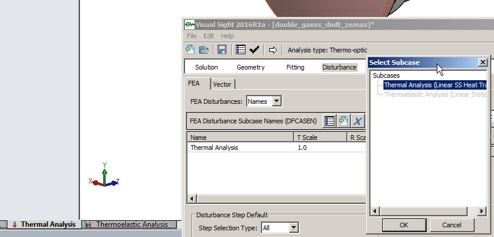
Define SolidWorks Simulation Study to Analyze
Surface entities are defined in a manner similar to their definition when interfacing to any other FEA software. Each surface references its vertex coordinate system and a solid body. A convenient browser feature allows the user to browse from within VSigFit the solid bodies of the SolidWorks Simulation model.
[margin20]
Using SigFit Analysis Results
Once the analysis is performed results may be imported into optical analysis models through macro files of surface rigid body motion and surface error characterized and written by SigFit.
[margin20]
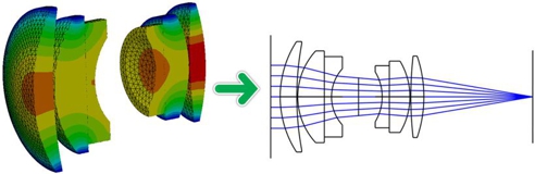
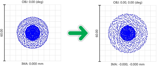
Within optical analysis performance metrics may be computed that quantify optical performance degredation due to the predicted mechanical disturbances. Shown below are nominal and disturbed spot diagrams of an imaging system using disturbance results from SigFit.
[margin20]